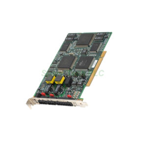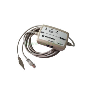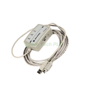
1746-IV32 SLC 500 32-Point Sourcing Input Module Installation & Maintenance
Product Introduction
The Allen‑Bradley 1746‑IV32 is a digital DC sourcing input module. It belongs to the SLC 500 family. This module offers thirty‑two input points in a single slot. It operates with 24V DC nominal voltage. The 1746‑IV32 uses a 40‑pin MIL‑C‑83503 type header. This connector requires a 1746‑N3 connector kit for wiring. Each input group has eight points per common. This configuration provides organized field wiring.
Users commonly apply the 1746‑IV32 in high‑density applications. It fits material handling and packaging lines. The module also serves conveyor systems and machine control. Its compact design saves valuable panel space. The 1746‑IV32 interfaces with standard DC sensors. It works with pushbuttons and selector switches. The module integrates easily into SLC 500 systems. This module ensures reliable signal acquisition. The 1746‑IV32 is ideal for discrete input applications with limited space.
Core Value
Firstly, the 1746‑IV32 delivers exceptional input density. You get thirty‑two points in one slot. This feature reduces chassis space requirements dramatically. Moreover, the module supports sourcing input configurations. This simplifies integration with standard sensors. In addition, the 1746‑IV32 provides reliable performance. Its operating voltage range is 15‑30V DC at 50°C. This range accommodates most industrial sensors.
Furthermore, the module offers easy diagnostics. Built‑in LEDs indicate each channel's status. This feature speeds up troubleshooting significantly. Specifically, the 1746‑IV32 draws only 50 mA at 5V DC. It draws 0 mA at 24V DC. This low power consumption reduces system load. Therefore, the 1746‑IV32 improves overall system efficiency. Besides, its compatibility with SLC 500 processors reduces integration effort. The module's robust construction ensures long service life. Ultimately, the 1746‑IV32 optimizes your control system performance.
Technical Insights
The 1746‑IV32 operates at 24V DC nominal voltage. Its input voltage range is 15‑30V DC at 50°C. The range reduces to 15‑26.4V DC at 60°C. This specification ensures reliable operation in warm environments. The module's nominal input current is 3.0 mA typical. Its ON‑state current is 2.0 mA minimum. The OFF‑state current is 1.0 mA maximum. These current values ensure proper sensor interfacing.
The module's backplane current draw is 50 mA at 5V DC. It draws 0 mA at 24V DC. This low draw minimizes power supply loading. The isolation voltage is 1500V AC for one minute. This rating protects against voltage surges. The 1746‑IV32 supports a 1.0 ms maximum response time. This speed handles high‑speed input signals effectively. The module uses group‑to‑group isolation. Each group of eight points shares a common return.
You can install the 1746‑IV32 in any SLC 500 chassis slot. The module automatically configures itself upon power‑up. No manual addressing or DIP switches are required. Therefore, setup is quick and straightforward. The module supports a wide operating temperature range of 0‑60°C. It meets NEMA and IEC industrial standards. The 1746‑IV32 is UL and CSA certified for global use.
Installation & Maintenance
Install the 1746‑IV32 in an SLC 500 chassis. First, power down the entire system. Then, insert the module into a free slot. Push firmly until the latch clicks securely. Use the 1746‑N3 connector kit for wiring. This kit provides the 40‑pin MIL‑C‑83503 type connector. Wire each input channel to the correct pins. Refer to the connector pinout diagram for accurate wiring.
Apply 15‑30V DC to input terminals for ON signals. Leave terminals open or grounded for OFF signals. The module supports sourcing inputs only. Therefore, connect the return path for each group. Each group of eight inputs shares a common return. Secure all wiring connections tightly. After wiring, power up the system. Check the module's LED indicators. Each LED illuminates when the corresponding input is active.
For maintenance, inspect all wiring connections periodically. Look for loose terminals or damaged cables. Clean the module with dry compressed air only. Avoid using any liquid solvents. Replace the module if LEDs fail to respond. Always test spare modules before installation. Keep the 1746‑IV32 away from moisture and excessive heat. Store spare modules in anti‑static packaging. Update your system documentation after any changes. Train maintenance personnel on proper handling procedures.
Use the diagnostic LEDs for routine troubleshooting. A lit LED confirms signal presence at that input. A dim LED may indicate low voltage conditions. No LED suggests a wiring or sensor issue. Verify the sensor's output voltage with a multimeter. Check the group return connection for continuity. Refer to the SLC 500 manual for specific error codes. Schedule regular system audits to ensure reliability.
Buyer’s Guide FAQ
Q1: What is the Allen‑Bradley 1746‑IV32 used for?
A1: The 1746‑IV32 reads 24V DC sourcing digital signals from sensors, pushbuttons, and switches in SLC 500 control systems.
Q2: Does the 1746‑IV32 support sinking inputs?
A2: No. The 1746‑IV32 supports sourcing input configurations only. Use the 1746‑IV16 for sinking or sourcing flexibility.
Q3: How many input points does the 1746‑IV32 provide?
A3: The 1746‑IV32 offers thirty‑two isolated DC input points in a single SLC 500 chassis slot.
Q4: What connector does the 1746‑IV32 use?
A4: The 1746‑IV32 uses a 40‑pin MIL‑C‑83503 type header. You need the 1746‑N3 connector kit for wiring.
Q5: How do I troubleshoot a non‑responsive 1746‑IV32 channel?
A5: Check the LED first. If off, verify wiring and supply voltage. Test the sensor separately. Replace the module if other channels work.