AI563 ABB S500 I/O Analog Input Module – Installation & Configuration Guide
Product Introduction
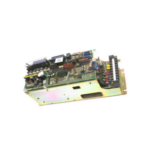
The ABB AI563 belongs to the S500 remote I/O system. Specifically, it provides eight differential analog input channels. Each channel accepts standard 4-20mA current signals. You connect pressure, temperature, or flow transmitters directly. Moreover, the module supports HART pass-through communication. This feature allows simultaneous analog measurement and digital HART data. Furthermore, the AI563 integrates with ABB AC500 PLCs and third-party masters via Profibus or Modbus. The module includes a 12-bit resolution ADC. Therefore, you get accurate process values for critical control loops.
Core Value
This analog input module offers three main benefits. Firstly, it reduces wiring costs. Eight channels fit into one compact housing. Secondly, it improves signal reliability. The AI563 provides channel-to-channel isolation. Consequently, ground loops disappear. Meanwhile, you can mix powered and passive transmitters. Thirdly, the module simplifies diagnostics. Each channel has a dedicated red LED for overrange or underrange conditions. Besides, the module supports hot-swapping. You replace a faulty unit without powering down the entire rack. Therefore, production uptime increases significantly.
Technical Insights
The AI563 operates on a 24V DC supply. Specifically, typical power consumption is 50 mA plus loop power. You must supply external 24V for each transmitter loop. The input impedance measures 250 ohms per channel. Additionally, the conversion time is 10 ms for all channels simultaneously. The module reports data in raw digital counts or scaled engineering units. For best accuracy, perform a two-point calibration annually. Moreover, the AI563 handles input currents from 0 to 25 mA. Above 25 mA, the module triggers an overrange flag. Use shielded twisted pair cables for all analog signals. Connect the shield to ground at the module end only.

Installation & Maintenance
Follow these steps for proper installation. Firstly, mount the AI563 on a standard S500 DIN rail. Secure the module with end clamps. Secondly, insert the removable terminal block. Torque the screws to 0.5 Nm. Thirdly, wire each transmitter correctly. For a 2-wire loop, connect the positive to pin 1. Connect the negative to pin 2. Meanwhile, configure the module addressing via the bus coupler. Use the ABB Automation Builder software to set input ranges. After power-up, verify the green PWR LED lights. The RUN LED should blink normally. Furthermore, clean the terminal block annually. Use isopropyl alcohol and a soft brush. Do not use compressed air near open terminals. Replace the module if you see persistent ERR LED.
Buyer’s Guide FAQ
1. What signal types does the AI563 support?
The AI563 accepts only 4-20mA analog current signals. It does not support voltage or thermocouple inputs.
2. Can I use the AI563 with non-ABB PLCs?
Yes. The AI563 works with any Modbus or Profibus master. You need the correct S500 bus coupler for your network.
3. What is the resolution of the ABB AI563?
This module provides 12-bit resolution. Therefore, you get 4096 steps across the 4-20mA range.
4. How do I troubleshoot a dead channel on the AI563?
Check the external 24V loop supply first. Then measure current at the terminal block. Finally, swap the channel with a known good one.
5. Does the AI563 support HART communication?
Yes. The AI563 passes HART digital signals. You need a separate HART multiplexer or master to decode the data.