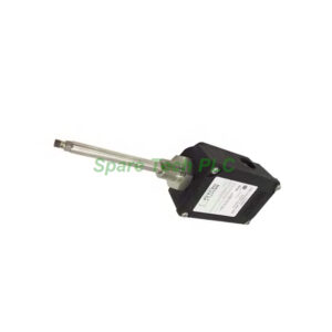
Bently Nevada 190501-12-00-01 Velocity Sensor Installation & Maintenance Guide
Product Introduction
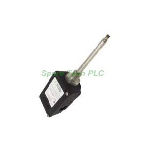
The Bently Nevada 190501-12-00-01 belongs to the Velomitor CT series. It is a low-frequency version of the standard piezo-velocity sensor. This model is a two-wire device that requires a 24 VDC power supply. It outputs a voltage signal proportional to the casing vibration velocity. Its primary application involves monitoring slow-speed rotating machinery. Specifically, engineers use it on cooling tower fan assemblies. It also monitors air-cooled heat-exchanger fans. These assets typically run at 100 to 300 rpm. The transducer provides reliable data for predictive maintenance.
Core Value
This transducer offers exceptional low-frequency response. It begins measuring at just 1.5 Hz. This capability allows it to capture critical data missed by standard sensors. The 190501-12-00-01 provides a sensitivity of 3.94 mV/mm/s (100 mV/in/s). Its stainless steel housing ensures durability in harsh environments. Additionally, the IP67 rating protects against dust and water ingress. Therefore, the sensor guarantees long-term reliability. Consequently, it helps reduce unplanned downtime in critical assets. Its compatibility with existing Bently Nevada monitoring systems simplifies integration.
Technical Insights
The Bently Nevada 190501-12-00-01 has specific ordering codes. The "12" in the model number designates a plate stud mounting option. Specifically, it is a 3/8-in 24 to M8x1 stud. The "00" indicates a MIL-C-5015 connection interface. Its frequency response is ±1 dB from 3 Hz to 900 Hz. It maintains ±3 dB response from 1.5 Hz up to 1.0 kHz. Furthermore, the device operates between -40°C and +85°C. The output bias voltage is 10.1 VDC ± 1.0 VDC. Finally, the user can extend cable lengths up to 305 m without signal degradation.
Installation & Maintenance
Proper installation is critical for the 190501-12-00-01 to function correctly. The mounting surface must be clean, flat, and stable. Securing the sensor requires the specified mounting torque. Use a torque of 4.5 N-m ± 0.6 N-m (40 in-lbf ± 5 in-lbf). Before installation, perform a visual inspection. Check the stainless steel case for cracks or corrosion. Also, verify the connector pins are clean. For maintenance, field tests can confirm functionality. A "tap test" checks the basic signal path. Furthermore, schedule periodic calibration checks to maintain accuracy. Ensure the cable shield is grounded at one end only to avoid ground loops. Finally, regularly inspect cable routing for wear or damage.

Buyer’s Guide FAQ
Q1: What is the primary application of the 190501-12-00-01?
A1: This model primarily monitors vibration on cooling tower fans and air-cooled heat exchangers operating at low speeds.
Q2: What power supply does this velocity sensor require?
A2: The 190501-12-00-01 is a two-wire loop-powered device. It requires a stable 24 VDC power source for normal operation.
Q3: How does the "12" suffix affect installation?
A3: The "12" suffix indicates a plate stud mounting option. Specifically, it means a 3/8-in 24 to M8x1 mounting stud.
Q4: What is the minimum measurable frequency for this transducer?
A4: This unit begins measuring at 1.5 Hz. Therefore, it captures data well below the standard 10 Hz cutoff of most sensors.
Q5: Can I extend the cable length beyond standard limits?
A5: Yes, the user can extend cables up to 305 m without degrading the output signal quality.