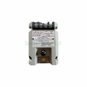
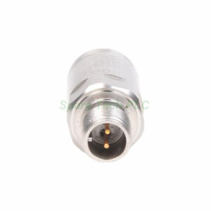
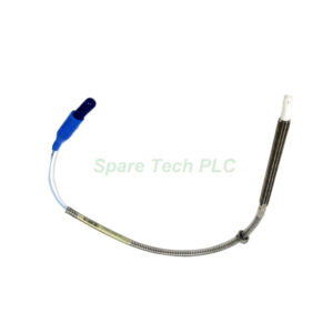
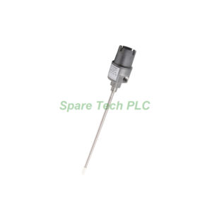
Bently Nevada 991-25-70-01-CN 991 Thrust Transmitter
Product Introduction
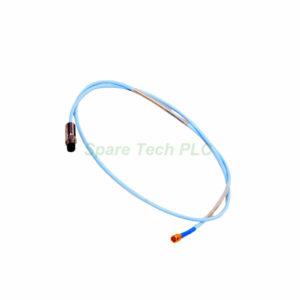
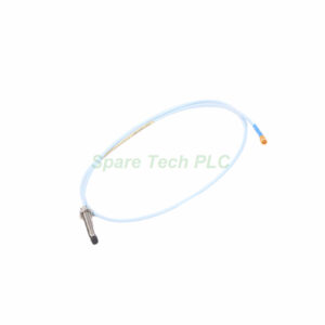
The Bently Nevada 991-25-70-01-CN belongs to the 991 series of thrust transmitters. This device accepts input from a non-contacting 3300 NSv proximity probe and extension cable. Additionally, it converts the probe signal into a standard 4-20 mA output for direct connection to PLCs, DCS systems, or panel meters.
This transmitter offers a bi-directional full-scale range of 25-0-25 mils and a 7.0-meter system length. Furthermore, it mounts on a standard DIN rail using bulkhead screws for secure installation. The 991 Thrust Transmitter is specifically designed for axial thrust monitoring in compressors, turbines, and other rotating machinery with thrust bearings.
Technical Specifications
This section details the core technical parameters of the 991-25-70-01-CN transmitter. The suffix codes precisely define its configuration for accurate ordering.
Full-Scale Option: 25-0-25 mils (bi-directional) (Suffix 25).
System Length: 7.0 meters (23.0 feet) (Suffix 70).
Mounting Option: Bulkhead screws on DIN rail (Suffix 01).
Agency Approval: Country specific (Suffix CN).
Input: Accepts 1 non-contacting 3300 NSv proximity probe and extension cable.
Output Signal: 4-20 mA (2-wire configuration).
Power Supply: +12 to +35 Vdc at the transmitter terminal.
Linear Range: 0.25 to 1.65 mm for Prox Out, suitable for 25-0-25 mils current loop linear ranges.
Maximum Loop Resistance: 1,000 Ω including cable at 35 Vdc.
Current Limiting: 23 mA typical.
4-20 mA Loop Accuracy: Within ±1.5% over the specified full-scale range (typical).
Mechanical and Environmental Parameters
The 991 Thrust Transmitter features a compact and rugged design for industrial environments. The transmitter weighs approximately 0.43 kg (0.9 lbm) and mounts securely on a DIN rail using bulkhead screws. This mounting method provides reliable installation in control cabinets and junction boxes.
For temperature performance, the transmitter operates from -35°C to +85°C (-31°F to +185°F). The storage temperature range extends from -51°C to +100°C (-60°F to +212°F), allowing for safe storage in extreme conditions. Meanwhile, the transmitter features non-interacting external zero and span adjustments, making calibration simple and convenient.
Electrical Characteristics
The Bently Nevada 991 transmitter offers robust electrical performance for reliable thrust monitoring. The 4 to 20 mA signal output operates in a 2-wire configuration, simplifying wiring and reducing installation complexity. The output covers the specified bi-directional full-scale range, with 4 mA representing -25 mils, 12 mA representing zero, and 20 mA representing +25 mils.
In addition, the maximum loop resistance is 1,000 Ω including cable at 35 Vdc, allowing for long cable runs to the control room. The current limiting feature protects the circuit at 23 mA typical. Furthermore, the NOT OK/signal defeat function forces the output below 3.6 mA within 100 µs after a fault condition occurs. The output restores within 0.1 seconds after the NOT OK condition clears, providing rapid fault indication.
Key Features and Benefits
The 991 Thrust Transmitter offers several distinct advantages for axial thrust monitoring applications. First, it accepts a 3300 NSv proximity probe directly, eliminating the need for separate signal conditioners. This simplifies the system design and reduces overall installation costs.
In addition, the bi-directional 25-0-25 mils range supports both positive and negative thrust measurements. This is essential for monitoring thrust bearing health in axial compressors and turbines. The non-interacting zero and span adjustments allow for easy field calibration without affecting other settings. Meanwhile, the rapid NOT OK response (within 100 µs) ensures that fault conditions are reported immediately to the control system. Consequently, the 991-25-70-01-CN provides reliable, cost-effective thrust monitoring for critical rotating machinery.
Installation Guidelines
Proper installation is essential for achieving optimal performance from the 991-25-70-01-CN transmitter.
First, mount the transmitter securely on a DIN rail using the bulkhead screws provided. Ensure the mounting location is clean, dry, and within the specified temperature range. Next, connect the 3300 NSv proximity probe and extension cable to the transmitter input. Then, verify that the probe is gapped correctly for the bi-directional linear range (0.25 to 1.65 mm).
After that, connect the 4-20 mA loop wiring to the transmitter terminals. Observe the correct polarity and ensure the power supply is within +12 to +35 Vdc. Finally, adjust the zero and span controls to calibrate the output for your specific thrust monitoring requirements.
Packaging List
The 991-25-70-01-CN unit is shipped new and original in factory packaging. The package contains the following items:
1 x Bently Nevada 991 Thrust Transmitter.
1 x 7.0 m system cable assembly.
1 x Set of bulkhead screws for DIN rail mounting.
1 x Installation instruction sheet.
Frequently Asked Questions (FAQ)
1. What is the difference between the 990 and 991 transmitters?
The 990 Vibration Transmitter measures radial vibration (0-10 mils pp), while the 991 Thrust Transmitter measures axial thrust (25-0-25 mils bi-directional). Therefore, you should select the model based on your specific monitoring application.
2. What probes are compatible with the 991 transmitter?
The 991 Thrust Transmitter accepts a non-contacting 3300 NSv proximity probe and extension cable. You should use Bently Nevada 3300 NSv series probes for proper compatibility and performance.
3. What is the maximum loop resistance for this transmitter?
The maximum loop resistance is 1,000 Ω including cable at 35 Vdc. Meanwhile, you should verify your total loop resistance to ensure it does not exceed this limit for reliable operation.
4. What shipping methods do you use for this item?
We ship this product using major international couriers. The shipping methods are typically Fedex, UPS, or DHL to ensure fast and reliable delivery worldwide.
5. How quickly does the NOT OK function respond to a fault?
The NOT OK function forces the signal output below 3.6 mA within 100 µs after a fault condition occurs. Then, the output restores within 0.1 seconds after the NOT OK condition clears, providing immediate fault indication to your control system.