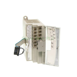
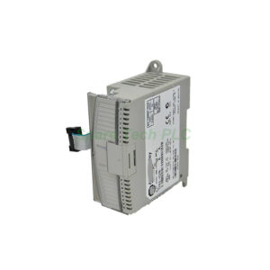
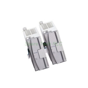
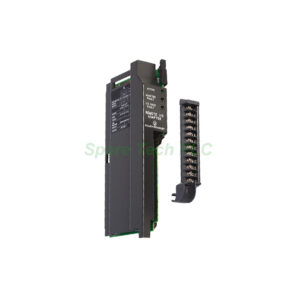
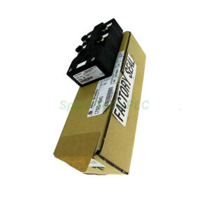
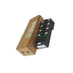
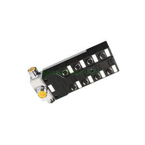
Allen-Bradley 1762-IR4 4-Channel RTD/Resistance Input Module
Product Introduction
The Allen‑Bradley 1762‑IR4 brings precision temperature measurement to your MicroLogix control system through four dedicated RTD or resistance input channels. This expansion module connects directly to MicroLogix 1100, 1200, and 1400 controllers, making it an ideal choice for process monitoring applications. The 1762‑IR4 accepts signals from a wide variety of RTD sensors, including Platinum 385, Platinum 3916, Copper, Nickel, and Nickel‑Iron types. Additionally, it handles pure resistance signals up to 3000Ω, which allows you to monitor potentiometers or resistive position sensors. Its Delta‑Sigma conversion technology delivers stable, accurate readings even in electrically noisy environments.
Supported RTD and Resistance Types
The 1762‑IR4 offers exceptional compatibility with nearly all common RTD sensor types. Specifically, it supports the following Platinum RTDs: 100Ω, 200Ω, 500Ω, and 1000Ω with both 385 and 3916 alpha coefficients. For Nickel‑based sensors, it accepts 120Ω Nickel 672 and 120Ω Nickel 618. It also supports 10Ω Copper 426 and 604Ω Nickel‑Iron 518 RTD elements. This broad coverage means you can standardize on the 1762‑IR4 across multiple temperature monitoring points without worrying about sensor compatibility.
For resistance input mode, the 1762‑IR4 accepts four standard ranges: 0 to 150Ω, 0 to 500Ω, 0 to 1000Ω, and 0 to 3000Ω. This flexibility enables you to connect resistive position sensors, slide potentiometers, or even strain gauges for displacement measurement applications.
Wiring Configurations
The 1762‑IR4 supports 2‑wire, 3‑wire, and 4‑wire RTD connections, giving you options to balance cost against measurement accuracy. For highest precision, use a 4‑wire configuration, which eliminates lead resistance errors entirely. A 3‑wire setup offers a good compromise, compensating for most lead wire effects while using fewer wires. The 2‑wire method is the most economical but assumes negligible lead resistance, making it suitable for short cable runs. For resistance devices, the 1762‑IR4 accepts both 2‑wire and 3‑wire connections. The terminal block includes a finger‑safe cover for safe and convenient wiring access.
Data Formats and Filtering
Once the 1762‑IR4 converts the analog input signal, it stores the value in a register using one of five configurable data formats. You can choose raw/proportional for direct unprocessed counts, engineering units x 1 for direct temperature readings, or engineering units x 10 for higher resolution. Additionally, the module offers scaled‑for‑PID format, which simplifies integration with built‑in PID loops, and percent full scale for percentage‑based applications.
To condition the input signal, the 1762‑IR4 provides six selectable input filters: 10 Hz, 50 Hz, 60 Hz, 250 Hz, 500 Hz, and 1 kHz. Lower filter frequencies offer better noise rejection, especially for 50 Hz or 60 Hz power line interference, while higher frequencies enable faster response times. Therefore, you can tailor the filter setting to match your specific application requirements.
Conversion and Update Time
The 1762‑IR4 uses a Delta‑Sigma conversion method, which provides high resolution and excellent noise immunity. The module's update time depends on the number of active channels and the selected filter frequency. For instance, using only one channel with a 1 kHz filter gives the fastest update rate. Conversely, activating all four channels with a 10 Hz filter results in the slowest cycle. Furthermore, enabling autocalibration and lead wire compensation adds extra time to each update cycle. The module can autocalibrate on channel enable, or you can program it to calibrate every 5 minutes for consistent long‑term accuracy.
Mechanical and Environmental Parameters
The 1762‑IR4 measures 90 x 87 x 40 mm and occupies a single slot in the MicroLogix expansion chassis. You can mount it on a standard 35 mm DIN rail or attach it directly to a panel using the integrated mounting holes. The module dissipates only 1.5 Watts of heat, allowing it to operate in compact enclosures with minimal airflow.
For reliable operation, install the 1762‑IR4 in a non‑hazardous, dry, and clean environment away from electrical noise sources and excessive heat. The operating temperature range is 0°C to 55°C (32°F to 131°F), with storage temperatures from -40°C to 85°C (-40°F to 185°F). Maintain relative humidity between 5% and 95% non‑condensing for best performance.
Compatibility and System Integration
The 1762‑IR4 integrates seamlessly with MicroLogix 1100, 1200, and 1400 controllers. The number of modules you can install depends on the specific controller model and its expansion capacity. For example, the MicroLogix 1200 supports up to four expansion I/O modules, while the 1400 series allows even more. Always consult your controller's manual to verify the maximum module count before planning your system.
This module communicates with the processor via the 1762 bus interface, receiving both 5V and 24V DC power through the backplane. It uses 6 input words for data and 5 configuration words for setup, providing comprehensive control over each channel's operation. A single diagnostic LED indicates both power and status, helping you quickly identify any issues. The 1762‑IR4 performs both module‑level and channel‑level diagnostics, reporting overrange, underrange, open‑circuit, and short‑circuit conditions for each input.
Installation Guidelines
When installing the 1762‑IR4, first ensure that the host controller supports the required number of expansion modules. Then, mount the unit securely on a DIN rail or panel. After mechanical installation, connect your RTD or resistance sensors to the removable terminal block, using the correct wiring scheme for your chosen configuration.
Always route input wiring separately from AC power cables to minimize electrical noise pickup. For RTD connections, use shielded twisted‑pair cables and ground the shield at one end only. After wiring, configure each channel's data format, filter frequency, and sensor type using your programming software. Finally, apply power and monitor the status LED to confirm proper communication with the controller.
Packaging List
Your shipment of the 1762‑IR4 includes the following items:
One Allen‑Bradley 1762‑IR4 RTD/resistance input module
One removable terminal block with finger‑safe cover
One quick‑start installation guide
Mounting screws for panel installation
Certification documents and warranty information are not included in this package.
Shipping Information
We ship all orders via FedEx, UPS, or DHL for fast and reliable delivery. Each package is carefully packed to prevent electrostatic discharge and physical damage during transit. Please allow 1‑2 business days for order processing before shipment.
Frequently Asked Questions
Q1: What RTD types does the 1762-IR4 support?
The 1762‑IR4 supports Platinum 385 and 3916 (100Ω, 200Ω, 500Ω, 1000Ω), Copper 426 (10Ω), Nickel 672 and 618 (120Ω), and Nickel‑Iron 518 (604Ω).
Q2: Can I connect a 2-wire RTD to this module?
Yes. The 1762‑IR4 accepts 2‑wire, 3‑wire, and 4‑wire RTD connections. However, for best accuracy, we recommend using 3‑wire or 4‑wire configurations.
Q3: What is the difference between the filter frequency settings?
Lower frequencies like 10 Hz provide better noise rejection, especially from power lines. Higher frequencies like 1 kHz give faster response times but less filtering. Choose based on your application's noise level and speed requirements.
Q4: How do I know if the module is working correctly?
The 1762‑IR4 has a single status LED. A steady green light indicates normal operation. If the LED is off or flashing, check the power connection and controller communication.
Q5: Does this module require external power?
No. The 1762‑IR4 draws all necessary power from the 1762 bus interface through the backplane, so no separate external power supply is needed.