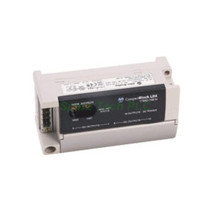
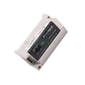
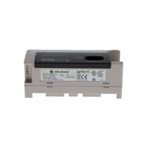
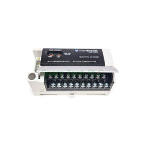
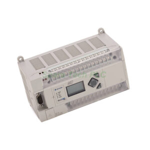
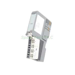
Allen-Bradley 1790D-N4C0 4-Channel Analog Current Input Module
Product Introduction
The 1790D-N4C0 from Allen‑Bradley brings four analog input channels to your DeviceNet system. Each channel accepts single‑ended, nonisolated current signals. You can configure the input range via software as either 4…20 mA (default) or 0…20 mA. This flexibility makes the module suitable for various sensors and transmitters.
Furthermore, the device delivers 12‑bit unipolar resolution. For the 4…20 mA range, each bit equals 3.90 µA. For the 0…20 mA range, each bit equals 4.88 µA. Converted data appears as binary values from 0000 to 0fff (max scale). The conversion time reaches 10ms per channel, ensuring steady data acquisition. Overall accuracy stays within 0.2% full scale at 0…55 °C. You will never need to calibrate this module in the field.
Technical Specifications
The 1790D-N4C0 features an input impedance of 249 Ω. Insulation resistance between insulated circuits measures 20 mΩ minimum at 250V dc. Photocoupler isolation separates I/O from logic, with a type test of 1250V ac rms for 60 seconds.
For power requirements, the DeviceNet supply accepts 11…28.8V dc (24V dc nominal) and draws up to 1.2 W at 28.8V dc. The field power supply needs 21.6…26.4V dc (24V dc nominal, +10%) and consumes 1.5 W maximum at 26.4V dc. Four red/green I/O status indicators give you clear visual feedback for each channel.
Mechanical and Environmental Data
This base module connects via a 37‑pin D‑shell connector. It can host up to two discrete expansion modules. The operating temperature range suits 0…55°C. Note that DeviceNet to logic is nonisolated, and field power is also nonisolated. Therefore, proper grounding practices are essential for reliable operation.
Installation Guidelines
First, mount the 1790D-N4C0 securely inside a suitable control cabinet. Then connect the DeviceNet cable to the network connector. Next, wire your analog sensors or transmitters to the 37‑pin D‑shell following the correct pinout diagram. After that, apply field power (24V dc nominal) and DeviceNet power separately. Finally, configure the input range for each channel using your software tool.
Meanwhile, avoid exceeding the maximum voltage ranges. Use shielded twisted-pair cables to minimize electrical noise. The module requires no calibration after installation, which reduces maintenance efforts significantly.
Packaging List
1 x 1790D-N4C0 Analog Current Input Module
1 x 37‑pin D‑shell connector (mating)
Quick start guide (printed)
Note: Certificates and warranty are not included in the package.
Shipping Methods
We ship worldwide via FedEx, UPS, or DHL.
Frequently Asked Questions (FAQ)
1. Can the 1790D-N4C0 accept both 4-20mA and 0-20mA signals?
Yes. You can configure each channel via software for either 4…20 mA (default) or 0…20 mA. This gives you great application flexibility.
2. Does the 1790D-N4C0 need periodic calibration?
No. The module requires no calibration at all. Its accuracy remains within 0.2% full scale over the entire 0…55°C temperature range.
3. How many expansion modules can I add to this analog base?
This base module supports up to two discrete expansion modules. Use them to increase your total I/O count on the same network node.
4. What is the conversion time per channel?
Each channel takes 10ms to convert the analog input to digital data. This speed works well for most industrial monitoring applications.
5. Is the 1790D-N4C0 isolated from the DeviceNet network?
No. DeviceNet to logic is nonisolated. Also, field power is nonisolated. However, I/O to logic uses photocoupler isolation for protection.